Buraxılış layihəsi
Buraxılış layihəsi “Code Academy”dəki təhsilin yekun layihəsi hesab olunur və çox önəmli rol oynayır. Təqdimat təhsil boyunca keçirilən bütün mövzuları özündə cəmləyir. Buraxılış layihəsi tədrisi
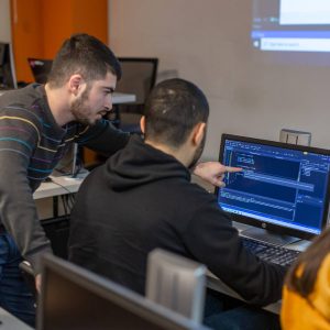
Praktiki tədris metodu
Hər hansı bir peşəni yaxşı bacarmaq üçün yalnız öyrənmək kifayət deyil, gərək öyrəndiklərinizi tətbiq edə bilmə bacarığına da yiyələnib təcrübə toplayasınız. Buna görə Code Academy-nin

Akademik Transkript
Tapşırıqlar, mini layihələr müəllim tərəfindən yoxlanılması sizin bilik və bacarıqlarının hansı dərəcədə olduğunu və həm tədrs müddətində, həm də məzun olduqdan sonra hansı sahələri daha

Mentor Sistemi
Mentor Sistemi Code Academy-də tələbələrin təhsildə öyrəndiklərini təkrar etmələrini və gücləndirmələrini təmin edən xüsusi bir sistemdir.
Code Academy bizə yalnız proqramlaşdırma öyrətmədi, həm də böyük bir həyat dərsi verdi. Risk etməkdən və xəyallarınızı izləməkdən qorxmayın. Heç vaxt gec deyil!

İlk dəfə Code Academy-ə gəldiyimdə, mühiti, əməkdaşları,
müəllimlərini gördüm və qərara gəldim ki, burda oxumaq istəyirəm.
müəllimlərini gördüm və qərara gəldim ki, burda oxumaq istəyirəm.

Code Academy-nin ən güclü tərəflərindən biri təbii ki, müəllim heyətidir. Müvafiq sahələri tədris eden şəxslər hal-hazırda öz sahələrinin mütəxəssisləridir. Xüsusilə tədris müddətində müəllimimiz Şahin Paşayevin əməyini ayrıca qeyd etmək istərdim.